PlanetKit is a project aimed at creating a toolkit for making interactive virtual worlds. I’m writing it in the Rust programming language, which I’m finding delightful to work with, and a great fit for the task.
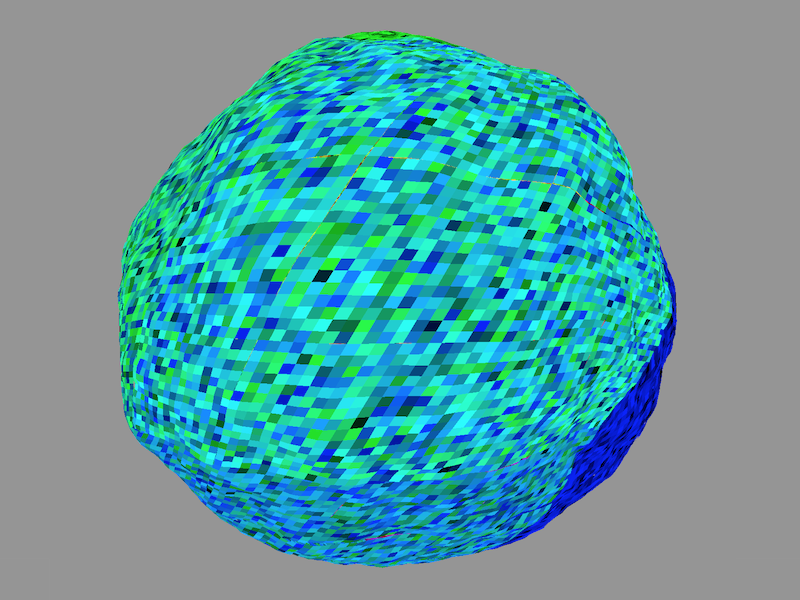
In my last post I used Perlin noise (now switched over to simplex noise) to create some basic terrain. Here’s the lumpy blob we ended up with at the end:
Let’s see what I said I was going to tackle next:
My next move will be to turn this into a proper voxmap of (mostly) hexagonal prisms, à la Minecraft. Or, you know, I might lie about that again and do something else instead.
Ok, then. Let’s do it! Errr, the voxels bit, I mean—not the lying.
The first thing I did was to change what I store about the globe from being a 2D array of height values (a heightmap) to a 2D array of enum instances representing whether the cell contains dirt, or air.
#[derive(PartialEq, Eq)]
pub enum Material {
    Air,
    Dirt,
}

// ...

pub struct Cell {
    // Removed this...
    // pub height: f64,
    // Added this...
    pub material: Material,
}
Then when I calculate the height of each cell on the globe, I either store Dirt if the cell we’re looking at is below the land elevation at that point, or Air otherwise, and only render the cell if it contains Dirt.
let material = if height > 1.0 {
Material::Dirt
} else {
Material::Air
};
cells.push(Cell {
material: material,
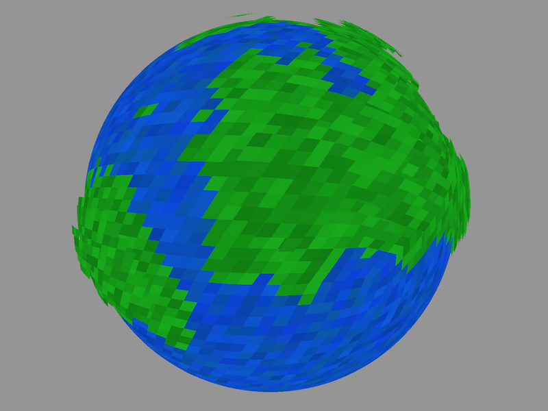
});Here’s what that looks like:
Cool! That’s a good start.
Voxels
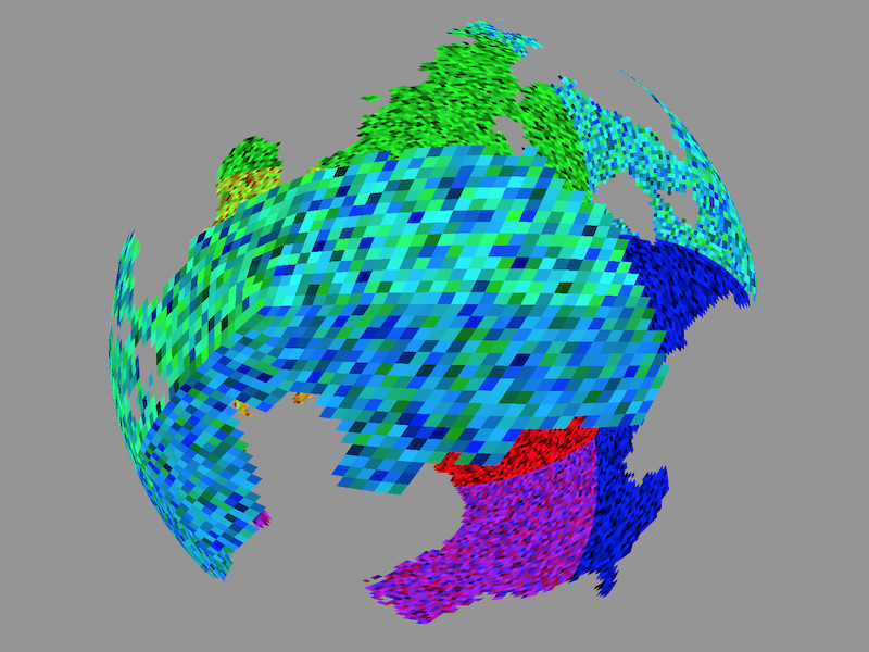
Before we get to hexagons, I want to turn this into a proper voxmap. So I made my chunks 3D, and stored the same thing as before (Dirt or Air) at each layer. That’s not much to look at yet, so I also introduced a third material type Water for wherever a cell is below sea level but above the land level at that point.
Hmmm, that’s not quite what I expected. There seems to be a surprising amount of water immediately next to land, and not just on the coastline. This turned out to be what I think of as equivalent to a kind of “z-fighting”. This came about because I had the sea level defined as 1.0 units from the center of the globe, and the way I was calculating the value of each cell, I would be evaluating the simplex noise at an elevation of almost exactly that same 1.0. My understanding is that in many cells, whether or not the ocean covered the land was then determined largely by tiny floating point errors.
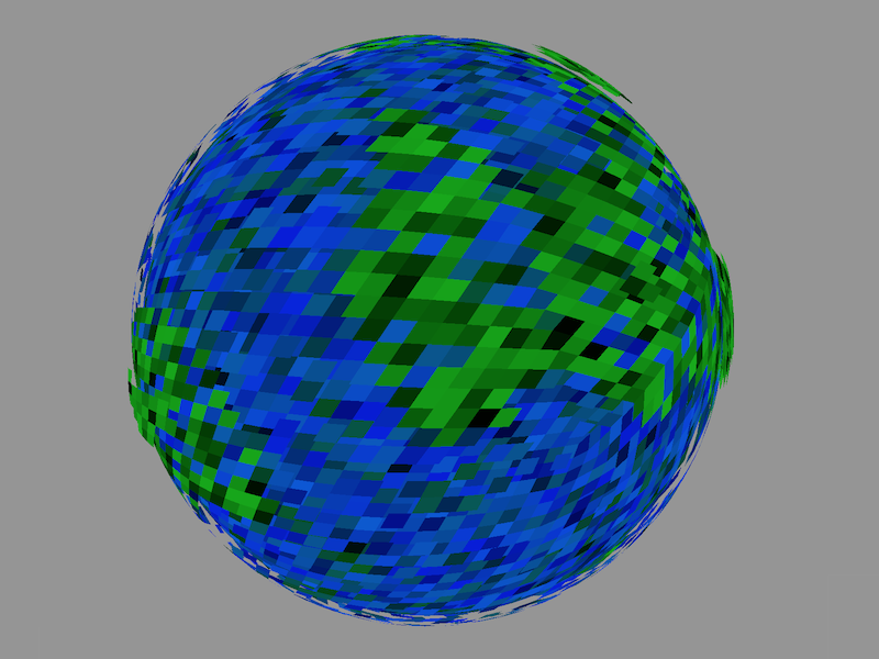
Changing the ocean radius slightly to something that doesn’t align so inconveniently with cell centers, e.g, 1.01, makes it look a lot better:
I think I also tweaked the colors between that screenshot and the one before, so the improvement in appearance is exaggerated. But you can clearly see that the coastline is better defined than before.
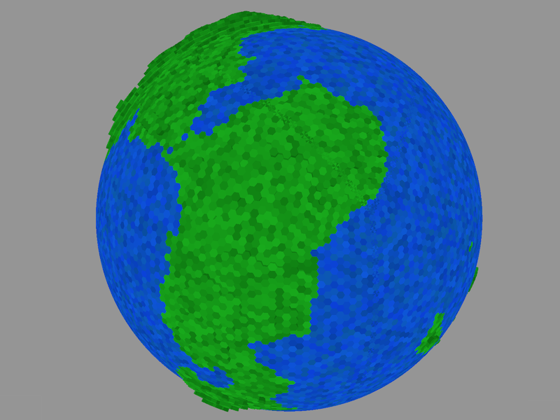
Hexagons, at long last
In all the screenshots until now, I’ve been drawing each cell in my world as a quad with one corner at the nominal center of the cell, and its opposite corner at the center of cell (x+1, y+1). This means they’ve been both offset a bit from where they’re supposed to be, and also obviously the wrong shape.
So how can I turn those quads into the hexagons I’ve been intending them to be all along? This is usually the point where I start scribbling on the back of envelopes (I think it was a parking fine in this case) to better understand the problem. What I came up with was a hexagon that wraps in both directions—and therefore can be tiled—positioned such that its center exists at all four corners of the quad:
(0, 0)
        ●       y
  x        ◌      ↘
  ↓     ◌     ◌
           ◌     ●
        ◌     ◌ /   ◌
           ◌   / ◌     ◌     (0, 0)
        ●-----●     ◌     ●
           ◌   \ ◌     ◌
        ◌     ◌ \   ◌     ◌
           ◌     ●     ◌
        ◌     ◌   \ ◌     ◌
           ◌     ◌ \   ◌
        ●     ◌     ●-----●
(0, 0)     ◌     ◌ /   ◌
              ◌   / ◌     ◌
                 ●     ◌
                    ◌     ◌
                       ◌
                          ●
                             (0, 0)
This makes it visually obvious that we’re dealing with a grid of 6 units between hexagon centers (count it) to calculate cell vertex positions (assuming we want all vertices to lie at integer coordinate pairs) as opposed to the grid of 1 unit between cell centers when we’re only concerned with the center points of each cell.
From there, if we list out points for the middle of each side and each vertex, starting from the middle of the side facing the positive x direction and travelling counterclockwise, we end up with 12 offset coordinate pairs in this grid, labelled as follows:
               6
      7                 5
         ●-----●-----●
        /   ◌     ◌   \
       / ◌     ◌     ◌ \
   8  ●     ◌     ◌     ●  4
     /   ◌     ◌     ◌   \
    / ◌     ◌     ◌     ◌ \
9  ●     ◌     ●     ◌     ●  3
    \ ◌     ◌     ◌     ◌ /
     \   ◌     ◌     ◌   /
      ●     ◌     ◌     ●
  10   \ ◌     ◌     ◌ /   2
        \   ◌     ◌   /         y
         ●-----●-----●           ↘
     11                 1
               0

               x
               ↓
Referring to the top figure for the offsets and the bottom for the labelling, that gives us:
- 0: (3, 0)
- 1: (2, 2)
- 2: (0, 3)
- 3: (-2, 4)
- 4: (-3, 3)
- 5: (-4, 2)
- 6: (-3, 0)
- 7: (-2, -2)
- 8: (0, -3)
- 9: (2, -4)
- 10: (3, -3)
- 11: (4, -2)
Plugging this in where the quads were before gives us this:
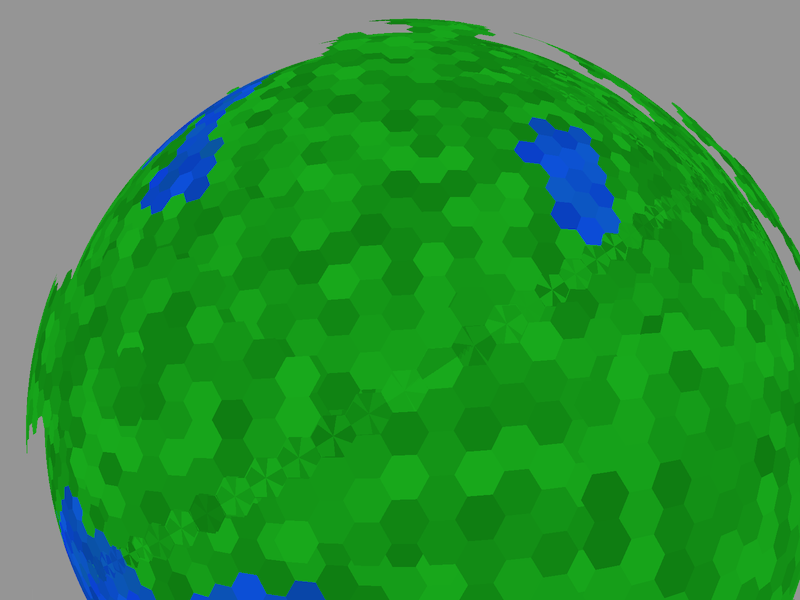
Yay, hexagons! But what’s the deal with that line of funny star things? Those happen where a particular cell is being drawn by two different chunks where they meet. Does that mean I have an off-by-one error? No—this is actually intentional.
Whilst one chunk will eventually have to own the data for each boundary cell (otherwise how will I know what is the authoritative state of the cell?), I’m intending that a chunk will render only the part of the boundary cells that fall within the bounding quad for that chunk. So eventually I’ll fix this so that each chunk will render its boundary cells using, e.g., these vertices instead:
               6
      7                 5
         ◌ · · ●-----●
        ·   ◌  │  ◌   \
       · ◌     ◌     ◌ \
   8  ◌     ◌  │  ◌     ◌  4
     ·   ◌     ◌     ◌   \
    · ◌     ◌  │  ◌     ◌ \
9  ◌     ◌     ●     ◌     ●  3
    · ◌     ◌  │  ◌     ◌ /
     ·   ◌     ◌     ◌   /
      ◌     ◌  │  ◌     ◌
  10   · ◌     ◌     ◌ /   2
        ·   ◌  │  ◌   /         y
         ◌ · · ●-----●           ↘
     11                 1
               0

               x
               ↓
Again, that’ll be easy to calculate now that we have the offset coordinates for the vertices of the hexagon, and the middle of each edge. (Were you wondering why I’d marked those edges in the diagrams above?)
To decide which chunk owns which cell’s data, I’m intending to do something roughly equivalent to (or possibly identical to, for lack of a better idea) this approach that was used by a bunch of atmospheric scientists a while back.
Gaps!
Flying around the globe revealed this problem:
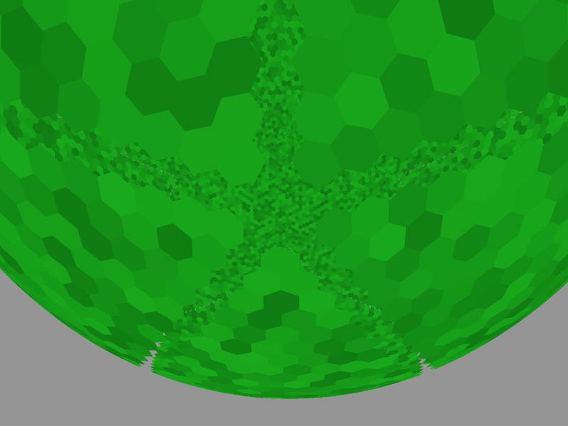
This one is an off-by-one error. The overlaps we saw in the previous image were showing up along the intersection of x = 0 in one chunk and y = 0 in the next chunk over. So where the chunks go to at the other corner doesn’t make any difference there. But I’d been rendering quads in a chunk from x = 0 to x = chunk_width - 1. This works for quads that go from where one hexagon center should be over to another, but for actual hexagons I need to render cells all the way from x = 0 up to x = chunk_width, or where chunks intersect at their other end, then neither chunk will be trying to draw hexagons there.
So that was easily fixed.
Hexagonal prisms
Now that we’ve got hexagons all over the place, it’s not much of a stretch to give them some sides to turn them into hexagonal prisms:
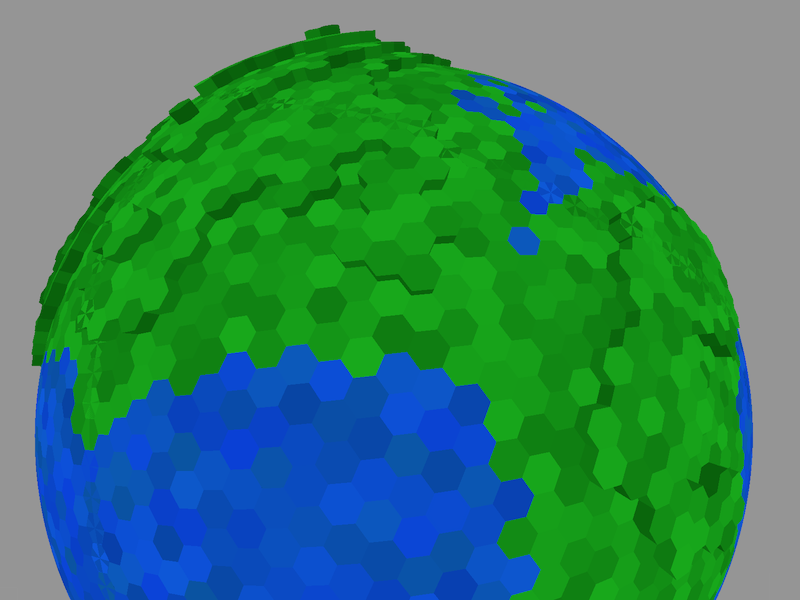
Sweeeeet. By the way, I haven’t implemented any lighting yet. The sides only look a bit like they’re in shadow because I’m halving the brightness of their colour across the board.
Let’s move a bit closer:
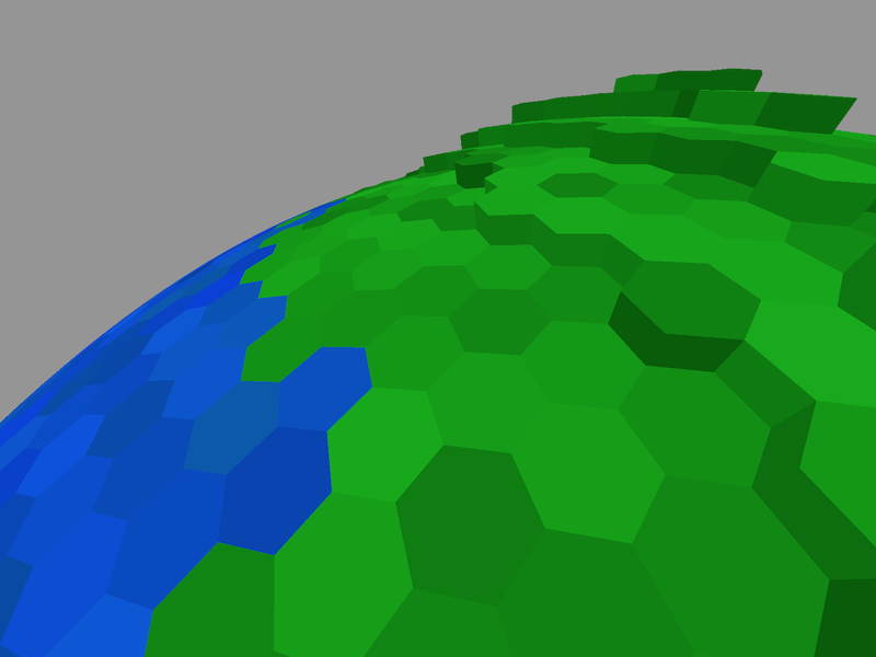
And a bit closer again… oops, we’re inside the world!

This very quickly reveals the next problem I need to solve: huge amounts of unnecessary geometry. This is about as high as I could crank up the resolution on the globe before my computer started begging for mercy.
The initial solution here will be to only render each side of a cell if the next cell over is air, because at least for now that’s the only way that side should ever be seen. I’ll need to get a bit more sophisticated than that eventually, but for now that will make things about a bajillion times better (give or take a few squillion).
What’s next?
Rendering the globe as a voxmap of hexagonal prisms is a pretty neat milestone. But I’m intending to majorly ramp up the complexity of this thing soon—more complex terrain generation, more types of cells, much higher-resolution terrain—so I’ll need to do a little bit of boring housekeeping before I move on to those other more glamorous things.
Specifically, I need to:
- Fix the rendering of cells at chunk boundaries (see above).
- Don’t render sides of cells that aren’t visible at all.
- Split out separate modules for generating terrain and rendering chunks. I’m not going to bother optimising any of this yet beyond the above, but I am going to keep in mind when design the interfaces a whole bunch of super-easy caching/memoization optimisations that I want to drop in later.
- Dynamically create and render chunks.
After that, I think I might take a swing at building a very simple game on top of this, both to demonstrate how I intend all the pieces of this to eventually fit together, and to make sure I put my money where my mouth is.